1. Background: The HDL Primer
The hardware description workflow starts at an abstraction called register transfer level (RTL). For example, a simple adder can be described in SystemVerilog, the most widely used HDL, as follows:
module adder(
    input logic[7:0] a,
    input logic[7:0] b,
    output logic[7:0] sum
);
    assign sum = a + b;
endmodule
This is a behavioral description of the adder. Hardware can also have a structural description, which uses logic gates as its most atomic primitives. Structural descriptions are beyond the scope of this discussion.
At first glance, this SystemVerilog code might look like a software function that assigns a value to an output reference. In software, a function call transfers control flow to the function. In hardware description, module instantiation does not transfer control. Modules instead interact through signals (wires).
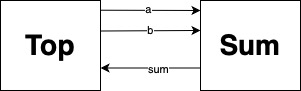
The signals are always connected and can be read anytime. The assign statement in the example above represents continuous assignment – meaning the value of sum is always the sum of a and b. There is no delay; the computation happens immediately. This is what is known as combinational logic in hardware. So whenever a or b changes, sum updates instantaneously. Essentially, the module behaves like a circuit that continuously computes the sum of its inputs.
Modelling Hardware Behaviours
Combinational logic models computations that are pure functions of the inputs. However, hardware behavior is often described using finite state machines. For this purpose, de-facto HDLs provide the abstraction of registers to model state-storing elements such as flip-flops and latches.
The system’s state is updated by a state function, which takes the current input and state values. Its output is the next state. This next state is assigned to a register on the next clock cycle.
For instance, consider the following SystemVerilog implementation of a counter:
module counter(
    input wire clk,
    input wire rst,
    output wire [7:0] cycle_count
)
    logic [7:0] cnt_n, cnt_q;

    assign cycle_count = cnt_q;
    assign cnt_n = cnt_q + 8'd1

    always_ff @(posedge clk or negedge rst) begin
        if(!rst) cnt_q <= 8'd0;
        else cnt_q <= cnt_n;
    end

endmodule
This code describes a component named counter. The component takes a clock signal clk and a reset signal rst as inputs. It produces an output signal cycle_count, which represents the current counter value.
The module body first declares two local variables, cnt_n and cnt_q, using logic. A SystemVerilog compiler or simulator infers whether a signal behaves as a wire or a register from how it is used.
The names follow a convention: for a state variable s, s_n denotes its next state and s_q stores its current state. Here, cnt is the state variable that stores the counter value.
After the declarations, two continuous assignments are defined:
assign cycle_count = cnt_q; and assign cnt_n = cnt_q + 8'd1.
The first assignment connects the output port cycle_count to the internal state register cnt_q. The second assignment defines the logic that computes the next state. This state function specifies that the next value of cnt_q is its current value incremented by 1.
The next state cnt_n is assigned to the state register cnt_q inside the always_ff block. The sensitivity list @(posedge clk or negedge rst) specifies that the assignment occurs either on the positive edge of the clock clk or on the negative edge of the reset signal rst. Intuitively, this means that the register is updated either during reset or on each clock cycle. Recall that the output signal cycle_count is mapped to the register cnt_q. Therefore, from the interacting module’s perspective, the component produces a new counter value on every cycle.
HDLs therefore define a programming paradigm in which the designer describes a state machine. Its state is stored in registers, and wires carry intermediate values derived from registers or constants. Interfaces are also modeled using wires. These interface wires carry values at all times, and their values are generally functions of the internal state.
Example: A Multiplier
Hardware designs often have a higher level state machine that defines the overall behavior of the component. Consider the following example of an 8-bit shift-and-add multiplier implemented in SystemVerilog:
TLDR : The shift and add algorithm is a simple multiplication algorithm that adds the multiplicand to itself based on the bits of the multiplier, shifting the result appropriately. For more details, refer to this link
module multiplier(
    input wire clk,
    input wire rst,
    input wire [7:0] multiplicand,
    input wire [7:0] multiplier,
    output reg [15:0] product
);
    // State definitions
    localparam IDLE = 2'b00;
    localparam CALC = 2'b01;
    localparam DONE = 2'b10;

    // Internal registers
    reg [1:0] state_n, state_q; // State register
    reg [7:0] H_n, H_q;      // Upper part of product register
    reg [7:0] L_n, L_q;      // Lower part of product register (contains multiplier)
    reg [7:0] M_n, M_q;      // Multiplicand storage
    reg [2:0] count_n, count_q;  // Counter (3 bits to count up to 8)

    assign product = {H_q, L_q};

    always_comb begin
        case(state_q)
        IDLE: begin
            H_n = 8'd0;
            L_n = multiplier;
            M_n = multiplicand;
            count_n = 3'd0;
            state_n = CALC;
        end
        CALC: begin
            // Check LSB of multiplier (L_q[0])
            if (L_q[0])
                H_n = H_q + M_q;  // Add multiplicand if the current bit is 1
            else
                H_n = H_q;

            // Shift right {H_q, L_q}
            {H_n, L_n} = {1'b0, H_q, L_q[7:1]};

            // Increment counter
            count_n = count_q + 3'd1;

            // Stop after 8 cycles
            if (count_q == 3'd7)
                state_n = DONE;
            else
                state_n = CALC;
        end

        DONE: begin
            state_n = IDLE;
        end


    end

    always_ff @(posedge clk or negedge rst) begin
        if (!rst) begin
            state_q <= IDLE;
            H_q <= 0;
            L_q <= 0;
            M_q <= 0;
            count_q <= 0;
        end
        else begin
        //Register updates
            state_q <= state_n;
            H_q <= H_n;
            L_q <= L_n;
            M_q <= M_n;
            count_q <= count_n;
        end
    end

endmodule
The output signal product is sourced from the registers H and L. That is, product updates immediately whenever H or L changes, which happens every cycle. The register H stores the upper half of the product, while L stores the lower half. The register M stores the multiplicand, and the register count keeps track of the steps of the algorithm. Since this is an 8-bit multiplier, the algorithm takes 8 cycles to complete. The register state stores the current state of the high-level state machine.
The always_comb block defines combinational logic. Its case block describes the high-level control state machine, which has three states:
IDLEinitializes values.CALCperforms the shift-and-add algorithm over the state.DONEindicates that multiplication is complete and the product is ready to be read.
Understanding the multiplier’s implementation is already somewhat tricky. The lack of human descriptions, comments, or clear naming conventions creates further challenges for an interfacing module. We will refer to this interfacing module as the Top module, as it is often called. A module that wants to use the multiplier faces several questions:
How does the Top module know when the product is ready?
How does the multiplier module know when to start computing? Does it expect new inputs every 8 cycles?
Without reading the implementation, can an interfacing module answer these questions by looking only at the interface definition?
Do compilers or synthesis tools help prevent incorrect usage of the module?
These questions highlight the need for better abstractions in HDLs for describing hardware components. That is where Anvil comes in.